What Is MLAG and Why It Matters in Production Networks
Multi-Chassis Link Aggregation (MLAG) is an Arista EOS proprietary feature that allows two independent physical switches to present themselves as a single logical switching entity to any connected device. From the perspective of a server, storage array, or downstream access switch, the MLAG pair appears as one LACP-capable peer. Both uplinks are active simultaneously, delivering full bandwidth utilization and sub-second failover when one peer or one link fails.
Traditional dual-homed designs using Spanning Tree Protocol (STP) block one uplink to prevent Layer 2 loops. This wastes half of the installed bandwidth and introduces STP convergence delays — typically 1 to 5 seconds for Rapid STP — during a link or switch failure. MLAG eliminates the blocked port entirely by synchronizing MAC tables, ARP tables, and LACP state between the two peers, allowing both uplinks to forward simultaneously with no STP involvement on the MLAG-connected segment.
MLAG is widely deployed at the access and aggregation layers of enterprise and data center networks: leaf switches running MLAG toward servers, or aggregation switches running MLAG toward access-layer distribution. Understanding how to configure, verify, and troubleshoot MLAG is a core skill for any Arista EOS operator.
MLAG Architecture and Component Overview
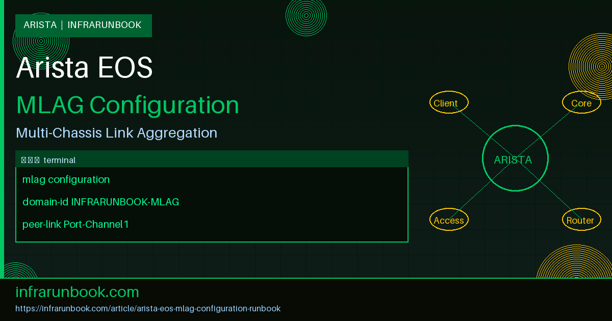
An MLAG deployment is built from four logical components that must all be correctly configured for the feature to operate:
- MLAG Domain: A named logical grouping identifying the two MLAG peers. The domain ID string must be identical on both switches.
- Peer-Link: A high-bandwidth port channel directly connecting the two MLAG peers. It carries inter-peer forwarded traffic, MLAG protocol messages, and serves as a failover path when a connected device's link to one peer goes down.
- Peer-Keepalive Link: A separate, lightweight UDP heartbeat path used exclusively to determine whether the remote peer is alive. This is the mechanism that prevents split-brain: if the peer-link fails but the keepalive is reachable, the secondary peer disables its MLAG interfaces instead of forwarding independently.
- MLAG Interfaces: Individual port channels on each peer, each assigned a numeric MLAG ID. The same MLAG ID on both peers logically bonds their respective port channels into one virtual aggregation group toward the connected device.
When fully operational, both peers share a virtual system MAC address. Connected devices negotiate LACP against this shared MAC, unaware they are physically connected to two separate switches.
Pre-Configuration Checklist
Before entering any configuration commands, validate the following:
- Physical peer-link cables are installed and connected between sw-infrarunbook-01 and sw-infrarunbook-02
- Management network connectivity between both switches is confirmed — verify with a ping across the management subnet before configuring keepalive
- Both switches are running compatible EOS versions (same major release is recommended; verify with
show version
) - VLAN database requirements are documented — every VLAN used on any MLAG interface must be present on both peers and allowed on the peer-link
- STP mode is consistent on both peers (this guide assumes RSTP)
- Port channel numbering convention is agreed upon — Port-Channel1 reserved for peer-link, downstream MLAG port channels start at 10 or higher
Step 1 — Configure Peer-Keepalive Addressing
The peer-keepalive runs over the management VRF in this guide. Each switch has a dedicated management IP address. The keepalive configuration references the remote peer's management IP.
sw-infrarunbook-01:
interface Management1
   ip address 192.168.1.11/24
   no shutdown
sw-infrarunbook-02:
interface Management1
   ip address 192.168.1.12/24
   no shutdown
Confirm bidirectional reachability before proceeding:
sw-infrarunbook-01# ping 192.168.1.12 source Management1
PING 192.168.1.12 (192.168.1.12) 72(100) bytes of data.
80 bytes from 192.168.1.12: icmp_seq=1 ttl=64 time=0.412 ms
80 bytes from 192.168.1.12: icmp_seq=2 ttl=64 time=0.388 ms
Step 2 — Build the Peer-Link Port Channel
Ethernet47 and Ethernet48 are bundled into Port-Channel1 using LACP active mode on both ends. This configuration is identical on both peers.
Both sw-infrarunbook-01 and sw-infrarunbook-02:
interface Ethernet47
   description MLAG-PEER-LINK-Eth47
   channel-group 1 mode active
   no shutdown
!
interface Ethernet48
   description MLAG-PEER-LINK-Eth48
   channel-group 1 mode active
   no shutdown
Verify both member interfaces are bundled before configuring the port channel further:
sw-infrarunbook-01# show lacp 1 peer
State: A = Active, P = Passive; S=ShortTimeout, L=LongTimeout;
       G = Aggregable, I = Individual; s+=InSync, s-=OutOfSync;
       C=Collecting, X=state machine expired, D=Distributing,
       d=default neighbor state
             |                        Partner                            |
Port    Status  |  Sys-id                   Port#  State    OperKey  PortPri |
------ -------- + ----------------------- ------ -------- -------- ------- +
Port Channel Port-Channel1:
Et47    Bundled  | 001c.7300.aabb,32768    0x002f ALGs+CD  0x0001   32768   |
Et48    Bundled  | 001c.7300.aabb,32768    0x0030 ALGs+CD  0x0001   32768   |
Step 3 — Create the MLAG Peer VLAN and SVI
By Arista convention, VLAN 4094 is reserved for MLAG inter-peer communication. A dedicated trunk group restricts this VLAN so it only traverses the peer-link and cannot leak to downstream access ports or other uplinks.
sw-infrarunbook-01:
vlan 4094
   name MLAG-PEER-VLAN
   trunk group MLAG-PEER
!
interface Vlan4094
   description MLAG-PEER-LINK-SVI
   no autostate
   ip address 10.0.0.1/30
   no shutdown
sw-infrarunbook-02:
vlan 4094
   name MLAG-PEER-VLAN
   trunk group MLAG-PEER
!
interface Vlan4094
   description MLAG-PEER-LINK-SVI
   no autostate
   ip address 10.0.0.2/30
   no shutdown
The
no autostatedirective is essential. Without it, Vlan4094 goes down if the VLAN has no active member ports, which can occur during a partial failure and would break MLAG peering at exactly the wrong moment. Now apply the trunk group to the peer-link port channel on both switches:
interface Port-Channel1
   description MLAG-PEER-LINK
   switchport mode trunk
   switchport trunk group MLAG-PEER
   no shutdown
Using a trunk group on the peer-link for VLAN 4094 is a critical security and stability practice. Without it, VLAN 4094 could be learned by downstream devices, introducing unexpected forwarding paths.
Step 4 — Configure the MLAG Domain
This is the core MLAG configuration block. The domain ID must be character-for-character identical on both peers. The local-interface points to Vlan4094. The peer-address points to the remote SVI. The peer-link identifies Port-Channel1. Reload-delay timers prevent forwarding before state synchronization completes after a reboot.
sw-infrarunbook-01:
mlag configuration
   domain-id INFRARUNBOOK-MLAG
   local-interface Vlan4094
   peer-address 10.0.0.2
   peer-link Port-Channel1
   peer-address heartbeat 192.168.1.12 vrf MGMT
   reload-delay mlag 300
   reload-delay non-mlag 330
sw-infrarunbook-02:
mlag configuration
   domain-id INFRARUNBOOK-MLAG
   local-interface Vlan4094
   peer-address 10.0.0.1
   peer-link Port-Channel1
   peer-address heartbeat 192.168.1.11 vrf MGMT
   reload-delay mlag 300
   reload-delay non-mlag 330
The
reload-delay mlag 300timer holds MLAG interfaces in a non-forwarding state for 300 seconds after a reload, allowing the switch to fully establish MLAG peering and synchronize its MAC and ARP tables before passing traffic. The
non-mlag 330value adds an additional delay for all other interfaces, ensuring MLAG converges before other protocols like BGP or OSPF begin advertising reachability.
Step 5 — Configure MLAG Interfaces for Downstream Devices
Each downstream device connects to both switches via standard LACP port channels. The MLAG ID integer is what logically ties the two peers' respective port channels together. The MLAG ID must be identical on both peers for the same downstream device.
In this example, a dual-homed server connects via Ethernet1 on each peer. Both peers form Port-Channel10 and assign MLAG ID 10:
Both sw-infrarunbook-01 and sw-infrarunbook-02:
interface Ethernet1
   description SERVER-DUAL-HOME-MEMBER
   channel-group 10 mode active
   no shutdown
!
interface Port-Channel10
   description SERVER-DUAL-HOME
   switchport mode trunk
   switchport trunk allowed vlan 10,20,30
   mlag 10
   no shutdown
A second downstream access switch connects via Ethernet2 on each peer, assigned MLAG ID 20:
interface Ethernet2
   description DOWNSTREAM-SW-MEMBER
   channel-group 20 mode active
   no shutdown
!
interface Port-Channel20
   description DOWNSTREAM-ACCESS-SW
   switchport mode trunk
   switchport trunk allowed vlan 10,20,30,40
   mlag 20
   no shutdown
The downstream server or switch running LACP sees a single LAG partner advertising the shared MLAG system MAC. It has no visibility into the fact that its two physical links terminate on separate switches.
Verifying MLAG Operation
After applying all configuration, use the following commands to confirm healthy MLAG state.
Overall MLAG Status
sw-infrarunbook-01# show mlag
MLAG Status:
state                    :          Active
negotiation status       :       Connected
peer-link status         :              Up
local-int status         :              Up
system-id                :  02:1c:73:aa:bb:cc
dual-primary detection   :        Disabled

MLAG Ports:
Disabled                 :               0
Configured               :               0
Inactive                 :               0
Active-partial           :               0
Active-full              :               2
The key fields to confirm: state = Active, negotiation status = Connected, and all expected MLAG ports in Active-full.
MLAG Interface Summary
sw-infrarunbook-01# show mlag interfaces
                                                              local/remote
 mlag       desc              state      local       remote          oper
------ ----------------- ----------- ----------- ----------- ------------
   10  SERVER-DUAL-HOME   active-full  Po10        Po10          up/up
   20  DOWNSTREAM-ACCESS  active-full  Po20        Po20          up/up
Configuration Sanity Check
sw-infrarunbook-01# show mlag config-sanity
MLAG config-sanity report

No configuration inconsistencies detected.
Peer Reachability
sw-infrarunbook-01# show mlag detail
...
Peer address            : 10.0.0.2
Peer link               : Port-Channel1
Peer link status        : Up
Keepalive status        : Up
Keepalive IP            : 192.168.1.12
System MAC              : 02:1c:73:aa:bb:cc
Domain ID               : INFRARUNBOOK-MLAG
...
Troubleshooting Common MLAG Problems
Negotiation Status: Disconnected
This means the peer-link is up at Layer 1/2 but MLAG protocol messages are not being exchanged. The most common cause is a missing or incorrect trunk group on Vlan4094 or Port-Channel1. Verify:
sw-infrarunbook-01# show interfaces Vlan4094
Vlan4094 is up, line protocol is up (connected)
  Hardware is Vlan, address is 001c.7300.aabb
  IP address is 10.0.0.1/30
sw-infrarunbook-01# show running-config | section interface Port-Channel1
interface Port-Channel1
   switchport mode trunk
   switchport trunk group MLAG-PEER
If the trunk group is missing from either interface, reapply the configuration. Also confirm VLAN 4094 exists in the VLAN database on both peers.
Split-Brain: Peer-Link Down, Keepalive Up
When the peer-link fails but the keepalive remains alive, EOS performs an automatic split-brain prevention: the secondary peer disables all its MLAG interfaces. You will see:
sw-infrarunbook-02# show mlag
MLAG Status:
state                    :       Secondary
negotiation status       :  Peer-link-down
peer-link status         :            Down

MLAG Ports:
Disabled                 :               2
The primary continues forwarding normally. Restore the peer-link physical connectivity to recover full MLAG operation. MLAG interfaces on the secondary will re-enable automatically once the peer-link is restored and state has re-synchronized.
MLAG Interface in active-partial
An active-partial state means the port channel is up on the local switch but the corresponding member interface is down on the remote peer. Traffic continues through the local peer only:
sw-infrarunbook-01# show mlag interfaces
   10  SERVER-DUAL-HOME  active-partial  Po10  Po10    up/down
Investigate the remote peer's physical interface:
sw-infrarunbook-02# show interface Ethernet1
Ethernet1 is down, line protocol is down (notconnect)
Check physical cable seating, SFP status, and confirm the connected device's NIC is active on that port.
Config-Sanity Violations
sw-infrarunbook-01# show mlag config-sanity
MLAG config-sanity report

  Local            Peer             Description
  -----            ----             -----------
  Vlan30 present   Vlan30 absent    Vlan30 only present on local switch
  STP mode RSTP    STP mode MSTP    STP mode mismatch between peers
Each reported inconsistency requires correction. Add the missing VLAN to the peer and align STP mode. Config-sanity violations do not always prevent MLAG from operating, but they indicate configurations that can cause silent forwarding issues or unexpected loop prevention behavior.
Production Best Practices
- Overprovision the peer-link: The peer-link carries all traffic that must cross from one peer to the other — including all BUM (Broadcast, Unknown Unicast, Multicast) traffic and any unicast destined for a MAC learned only on the remote peer. Use at least 2x40GbE or 2x100GbE links in the peer-link port channel.
- Isolate the peer-keepalive path: Never route keepalive traffic over the same links used for data. Use the management VRF or a dedicated point-to-point link. If the keepalive and peer-link share the same physical path, a single failure could cause split-brain.
- Always configure reload-delay timers: Without these, a switch returning from a reboot may begin forwarding MLAG traffic before it has synchronized MAC and ARP tables with the peer, causing transient packet loss.
- Keep VLAN databases synchronized: Any VLAN active on an MLAG interface must exist in the VLAN database on both peers. Automate VLAN provisioning using CloudVision or configuration management tools to prevent drift.
- Use identical STP bridge priorities on both peers: Both MLAG peers should be configured as STP root for all relevant VLANs to prevent the downstream device from making unexpected STP topology decisions based on perceived bridge priorities.
- Run show mlag config-sanity after every change: This command is the fastest way to catch configuration drift between peers before it causes a production incident.
- Monitor MLAG state with syslog or CloudVision alerts: Configure alerting on state transitions such as peer-link-down, negotiation-disconnected, or active-partial MLAG interfaces. These events are always operationally significant.
- Test failover in a maintenance window: Manually shut the peer-link port channel and verify that the primary continues forwarding and the secondary disables its MLAG interfaces as expected. Restore and verify re-convergence.
Related Articles
- [Arista] Arista EOS BGP EVPN VXLAN: Complete Run Book for Leaf-Spine Data Center Fabrics
- [Arista] What Is Arista EOS and How It Differs from Cisco IOS
- [Arista] Arista EOS VLAN & Trunk Configuration: Complete Run Book for Access Ports, Trunk Ports, and Inter-VLAN Routing
- [Arista] Arista BGP EVPN VXLAN Leaf-Spine Architecture